|
|
GENERAL EQUIPMENT INC.
8724 Sunset Drive #191● Miami FL 33173 · USA
|
|
|
GENERAL EQUIPMENT INC.
8724 Sunset Drive #191● Miami FL 33173 · USA
|
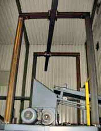
USED TIRE PLANT
|
TYPE: |
Plant |
|
DESCRIPTION: |
Used Tire Recycling Plant |
|
PRICE: |
Upon Request |
|
PACKING: |
As is, Where is |
used tire recycleing plant
Subject
Unsold or Market Withdrawal


|
GREEN TECHNOLOGY
Green Technologic Park
Green Technolog-ic Park is specialized in manufacturing waste tires/plastics to fuel oil Thermolysis machine and waste oil to diesel distillation machine since 1993, have been a leader of oil pyrolysis plant field for 20 years.
After years of re-search and development, we have obtained 11 patents and CE & ISO certificates related to our machine.
Through the efforts of our domestic and international sales team, we’ve already sold our machine to more than 34 countries all over the world.
With 30 experienced engineers for overseas after sales service. In alliance with our partners, we have more than 2.000 square meters running demo plant for customers’ visitation and learn-ing.
Waste plastic pyrolysis plant, with the superiority of low capital investment and high fuel financial price, it has become the first preferred waste disposal method in many countries.
This profitable project was established every week with low labor costs and high profits.
Now we did it, we invented the waste plastic pyrolysis machine converting waste plastics into fuel oil with green energy.
It could ease the energy shortage and create huge economic benefits.
Green Techno-logic Park, the products main-ly include waste plastic refining equipment, waste tires oil refining equipment, waste oil refining equipment, fuel oil purification equipment, distillation machine, municipal solid waste sorting equipment, dust removal equipment.
The company has experts, engineers, technicians of the technical development team, in order to meet the special requirements of customers products.
We also sup-ply turnkey waste tire and plastic, to diesel machine, the complete processing line can recycle waste tires, plastics and rubbers into diesel oil.
Layout
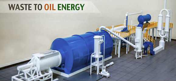
Waste to Oil Energy
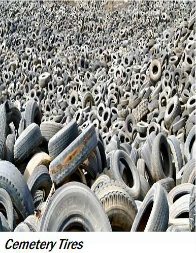
In most countries people handle waste tires and plastic with landfill or burning. But it causes serious pollution to environ-ment and could probably lead to fire dis-aster or disease spread. By contrast, py-rolysis plant is a green way for waste management.
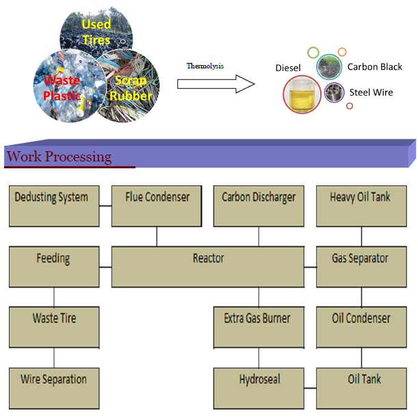
The raw materials can be used tires, waste plastic, scrap rubber which can be easily found from rubbish collecting station. The cost of raw materials is low, even you can get subsidy by solving pollution caused by garbage in many countries. Meanwhile the fuel oil finds a good market in many industry fields. In the whole process, we adopt the international advance mode and also pay more attention to the combination between the introduction of technology and independent development, on the product quality, we continuously move to a higher level.

Composition of System
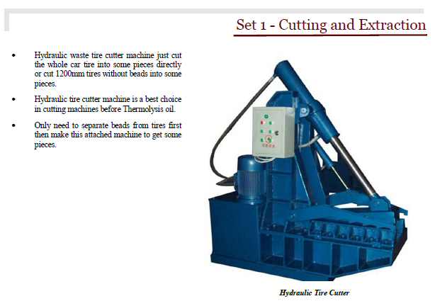
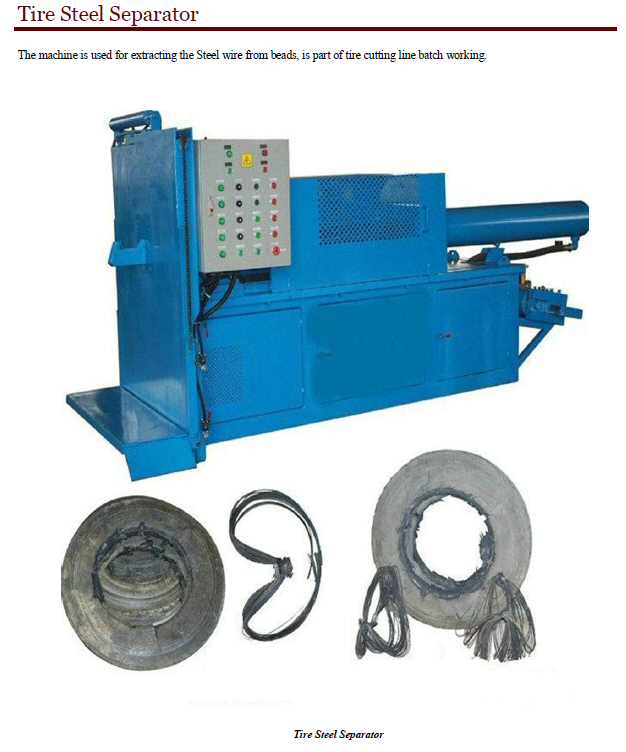
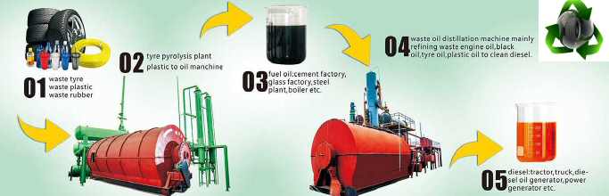
Firstly, cut the tire and remove the wire, second, put the raw material into furnace, then seal the feed inlet system. Thirdly, burn the fuel material (coal, or wood, or natural gas, oil ) in the com-bustion system, the reactor will slowly be heated ,when the temperature reach-es around 80-100 degree Celsius, It will produce oil gas, oil gas will be processed by our technology ,then goes to the cooling system-condensers to be cooled down then go to the first heavy oil tank. the other oil gas which can not be liquefied under normal pressure and normal temperature ,can be recycled going into the furnace instead of the fuel materials to heat the reactor, which can save energy very much . After finishing oil produce ,the temperature of reactor will be down, at the same time, carbon black will be discharged automatically. Then you can start another batch working.
The system is composed of 4 sets, as follows:

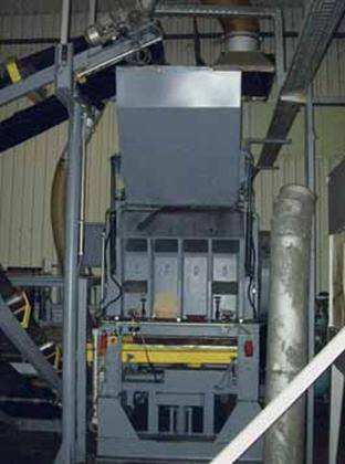
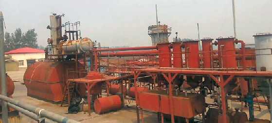
Thermolysis System
First, Let's talk about "WASTE TO ENERGY" project. In one word, WTE means the process of converting waste tire/plastic/engine oil/ to useful fuel oil and valuable diesel. See what can we benefit: WTE processes will make an impact on our environment and will be a quite lucrative investment. This WTE process eliminates landfills, piles of used tires, asbestos, and toxic material by converting the waste into electricity, fuel, steam, construction/highway aggregate, and a superior insulation and creates jobs.
Waste tire thermolysis is a recycling technique that converting plastic or tire waste into industrial fuels like oil, monomers, or other valuable materials by thermal and catalytic cracking processes like carbon black, steel wire and hydrocarbon gas. It allows the treatment of mixed, unwashed plastic wastes.
We have standard laboratory can test kinematic viscosity. We also have CE, ISO 9001:2000 and ISO 14001, and (9) nation-al patents.
Equipments:
Reactor 16mm Thickness.
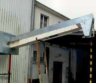
Feeder System.
Foundation.
Integrated Cooling System (German Technology).
Dedusting System.
Catalyst Chamber.
Electric Cabinet (Control Panel).

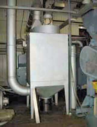
Distillation System
The distillation machine mainly consist in the temperature control to get diesel. Our technologies is not only making profit for you but also helping the environment. Distillation Machine Working Process:
First, pump the waste oil into reactor by oil pump.
Second, use coal, wood, natural gas, fuel oil or electricity heating the reactor.
Third, after heating some time, the liquid oil will become oil gas, oil gas will be liquefied by the cooling pipe and conden-sers then will go into oil tank. Here we get mixed oil, or can also call it fuel oil. If you want get diesel and gasoline sepa-rately, through temperature control could separate it and col-lected into two different oil tanks.
Fourth, some gases (syngas) like Methane, Ethane, Propane, Butane, and Hydrogen cannot be liquefied under normal pres-sure and normal temperature will be recycled to fire furnace heating the reactor.
Fifth, when use burning material heating the reactor, will pro-duce some smoke. These smokes will go into our de-dusting system, the inside we design some high pressure nozzles, the-se nozzles will spraying some chemical water, the dust will be absorbed by the chemical water and flowing into the de-dusting pool. In the pool we will put some chemical which could remove the sulfur.
Sixth, the exhaust gas will go into the chimney sucked by draft fan, when emission the exhaust gas will become steam, no pollution.
Equipments:
Cooling System (6th Generation Oil Distillation Plant).
Decolor and Desmelling Device.
Liquid Color Removing Tank.
Solid Color Removing Tank.
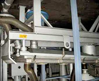
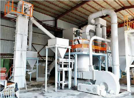
Carbon Black Processing Plant
High Pressure Ultrafine Grinder is is widely used in non-metal minerals industry, and features many advantages: stable performance, wider application range, simple structure, easy operation, high capacity, energy conservation, environmental protection, etc. It is a kind of high-tech grinding product, and is used to grind barite, limestone, kaolin, and ceramics and slag, whose Mohs hardness is below 9.3 scales, non-inflammable and non-explosive material.
The grinding Process of the Main Mill is that the transmission device brings along the Central Shaft to drive. The upper part of the shaft connects with the Quincunx Rack, on the frame is loaded with the roller assembly, and forms a swinging pivot. The central shaft does revolve around the central rotation, at the same time it revolves around the grinding rings, and itself also rotates on account of the grinding effect. The shovel sys-tem, in the lower part of rollers, is loaded on the lower part of the Quincunx Rack. In the process of rotating of the shovel and the roller, the material will be fed gasket layer between the rollers and ring. The outside centrifugal force (compression force) yielding in this process will process the material into small powder, thus the desired powder is ob-tained (Carbon Black).
Equipments:
Mainframe.
Blower.
Classifier.
Bucket Elevator.
Electromagnetic Feeder.
Switch Electric Box.
Hopper
Features
1. Safety. We treat safety as the first important thing in produc-tion.
Two devices to avoid back-fire in production: oil-water separator and anti-back fire device.
Vacuum device makes reac-tor working under ordinary pressure or negative pressure.
Temperature monitoring de-vice to avoid excessive work-ing temperature.
Pressure gage to monitor the pressure. If it goes above a certain level, the bell will alarm and the safety valve will release the pressure auto-matically.
Carbon black is discharged in a closed situation to avoid catching fire.
2. Environmental protection.
The flue gas (caused by burn-ing fuel to heat the reactor) will be purified and cooled by dust removal device, then can be released into air through chimney.
The procedure to remove carbon black is working un-der closed situation to avoid pollution.
3. High oil yield.
We have 3 steps for cooling system: one condenser pipe, two large horizontal conden-sers and two vertical conden-sers. The oil gas pass through 3 steps cooling system in se-quence. The total cooling area is 65 square meter.
When the oil gas pass through the condensers, it’s divided into several portions by small pipes inside conden-ser and be cooled separately.
In this way we maximize the cooling effect and improve the oil yield.
4. High oil quality.
The oil gas is purified by mo-lecular sieve inside catalyst chamber so that the quality of oil is higher.
5. Energy saving.
The flame path is designed as spiral so that the quantity of heat can be fully used.
The residual gas from pyroly-sis is recycled to furnace burning to heating the reac-tor.
The insulation cover is formed by 3 levels: steel plate, rock wool and refracto-ry cement. Excellent thermal insulation effect helps saving fuel.
6. High degree of automation.
In manufacturing we use auto cutting machine, auto weld-ing machine, auto rolling ma-chine so that both quality and appearance of our products can be guaranteed.
In production, we use auto-feeder to feed raw materials into auto-feeder. By auto-feeder it needs few workers and less time to feed. And because of 50 ton hydraulic pressure from auto-feeder, it can feed more tires than la-bor.
7. Long service life.
The material of reactor is Q345R boiler plate with 16/18mm thickness which is produced by well-known en-terprise. The head of reactor and accessories are using one-piece molding shell cover rather than welded plate.
All cutting, rolling and weld-ing works are finished by automatic machines.
We know quite well about the material quality and man-ufacturing process, that’s why we are confident in the service life of our products.
We also supply installation service, training service and one year warranty.
Specification and photos are not contractual and are subject to verification upon inspection
TAKE NOTICE!
PLEASE BE ADVISED THAT INFORMATION INCLUDED IS CONFIDENTIAL IN NATURE AND IS BASED ON PRE-EXISTING BUSINESS RELATIONSHIP WITH THE LEGAL OWNER OF PROPERTY DESCRIBED HEREIN (IF APPLICABLE). AS SUCH, UPON RECEIPT OF SAID INFORMATION THE RECEIVER ACKNOWLEDGES THAT ANY UNAUTHORIZED CONTACT WITH SAID LEGAL SELLER WILL BE CHARACTERIZED AS A BREACH OF CONFIDENTIALITY AND SAID AGREEMENT MAY BE ENFORCED UNDER EXISTING LAW OR IN EQUITY.
This paper was
prepared by General Equipment Inc.
The paper represents an offer of a partner of General Equipment Inc.
All rights are reserved by and for General Equipment Inc.
All
content and ideas of this paper are the property of General Equipment Inc.