|
|
GENERAL EQUIPMENT INC.
8724 Sunset Drive #191● Miami FL 33173 · USA
|
|
|
GENERAL EQUIPMENT INC.
8724 Sunset Drive #191● Miami FL 33173 · USA
|
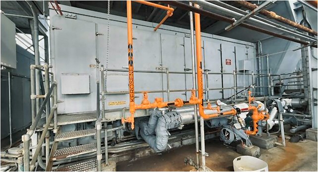
FRAME7
|
TYPE: |
Power Plant |
|
DESCRIPTION: |
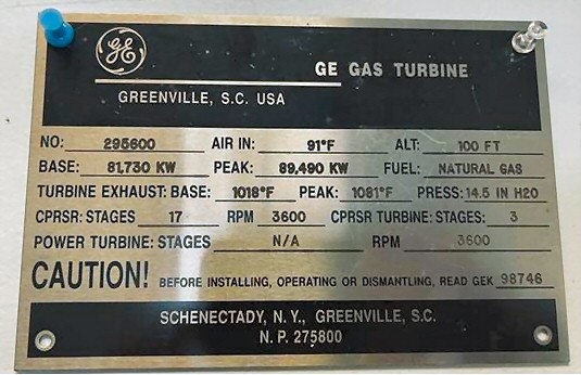
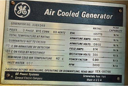
GE Frame 7EA Gas Turbine Power Plant |
|
PRICE: |
Upon Request |
|
PACKING: |
As is, where is |
GE FRAME 7EA GAS TURBINE POWER
PLANT
|
General Electric Frame 7EA Gas Turbine Generator Set Consist of Following: 3600 RPM CCW Rotation History: |
TAKE NOTICE!
PLEASE BE ADVISED THAT INFORMATION INCLUDED IS CONFIDENTIAL IN NATURE AND IS BASED ON PRE-EXISTING BUSINESS RELATIONSHIP WITH THE LEGAL OWNER OF PROPERTY DESCRIBED HEREIN (IF APPLICABLE). AS SUCH, UPON RECEIPT OF SAID INFORMATION THE RECEIVER ACKNOWLEDGES THAT ANY UNAUTHORIZED CONTACT WITH SAID LEGAL SELLER WILL BE CHARACTERIZED AS A BREACH OF CONFIDENTIALITY AND SAID AGREEMENT MAY BE ENFORCED UNDER EXISTING LAW OR IN EQUITY.
This paper was prepared by
General Equipment Corp.
The paper represents an offer of a partner of General Equipment Corp.
All rights are reserved by and for General Equipment Corp..
All
content and ideas of this paper are the property of General Equipment Corp.