|
|
GENERAL EQUIPMENT INC.
8724 Sunset Drive #191 ● Miami FL 33173 · USA
|
|
|
GENERAL EQUIPMENT INC.
8724 Sunset Drive #191 ● Miami FL 33173 · USA
|
9FIRETRUCKMB
|
TYPE: |
Fire truck |
|
DESCRIPTION: |
Mercedes-Benz 1823 K6 Fire Truck |
|
PRICE: |
Upon Request |
|
PACKING: |
As is, Ew-Works |
MERCEDES-BENZ 1823 K6 FIRE TRUCK
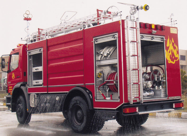
TECHNICAL SPECIFICATION FOR A FIRE TRUCK EXTINGUISHER WITH A 9 M PORTABLE LADDER
1. SUBJECT
1.1. These specification comprises the technical and other properties and characteristics of the fire truck extinguisher equipped with a high-pressure pump and a portable ladder, built unto a plain chassis of a truck, having a modular design, as specified in the technical specifications, to be purchased by the Fire Department of our municipality.
2. VEHICLE CHASSIS
2.1. Mercedes Benz 1823 K model.
3. EQUIPMENT
3.1 GENERAL
3.1.1. The fire truck extinguishing vehicle will be used for the fires which may arise within the city and suburb limit purposes. The superstructure of the vehicle shall be in compatible with TS EN ISO 9001 standards, of a modular design, built as a front cabin, a tank and a rear cabin.
3.2. BODYWORK
3.2.1. After the water tank is installed on the chassis, carcass cabins made of 40 x 30 profile shall be made along the width of the boiler at the front and rear sections of the water tank. After the profiles are processed, they will be coated with 1.2 mm DKP sheet metal. The top of the bodywork will be coated with 3-4 mm diamond shaped sheet metal. A longitudinal guardrail shall be installed at the upper section using ¾ inch pipes.
3.2.2. The equipment bodywork shall be manufactured in 3-piece, modular design, and can be easily disassembled when necessary.
3.2.3. The cabin doors shall be made of aluminum material, of blind type, and the water and dust impermeability of the doors shall be ensured.
3.2.4. The cabin doors shall have holding handles and security locks.
3.2.5. After bodywork is completed, it shall be painted, and it will be coated with nickel as required. The interior of the cabins shall be made of diamond shaped aluminum sheet metal.
3.3. WATER TANK
3.3.1. The capacity of the water tank shall be at least 7.000±100 (seven thousand plus minus one hundred) liters depending on the design.
3.3.2. The tank shall manufactured and installed with a modular design so as to allow easy disassembly for repair purposes.
3.3.3. The water tank shall be made of min. 4 (four) mm stainless Chrome-Nickel (Cr-Ni) sheet metal complying with AISI 304 standard, and the tank shall be welded uniformly from interior and exterior using the gas welding technique.
3.3.4. In order to eliminate the turbulences and free water surface levels arising from the movement of the vehicle, at least 4 (four) -at least 2 (two) transverse and at least 2 (two) longitudinal- jetties shall be installed inside the tank using the same material with the tank material. Using these partitions (jetties), at least 6 (six) compartments which shall have manholes for cleaning purposes shall be formed inside the water tank.
3.3.5. At the top of the tank, there shall be a manhole lid with rubber seal, with a size suitable for easy access of people, and which can be easily opened and closed
3.3.6. The upper surface of the tank shall designed to minimize skidding using diamond shaped sheet metal with milling facing up.
3.3.7. At the bottom, there shall be a sedimentation reservoir with a suitable diameter and a suitable depth, and the bottom of the reservoir shall be equipped with 1 (one) global valve of at least 2,5" (two point five inches) for the discharge of the waste.
3.3.8. A ladder with guardrail shall be mounted at the back or side of the vehicle for access to the upper platform.
3.3.9. An escape/gushing or bluff pipe with suitable size shall be installed with regard to the pump position in order to discharge the compressed air and extra water during the filling of the tank.
3.3.10. For external filling of the tank, two filling inlets of at least 2.5" (two point five) with slide and sleeve shall be fitted at left and right sides. At the interior section of the filling inlet, a pipe with a diameter of at least 2.5” (two point five) which shall extend up to the ceiling of the tank, but shall not touch the ceiling shall be fitted to ensure the filling of water without facing any pressure.
3.3.11. The water tank module shall have special profile imprints at sides in accordance with the shape of the vehicle.
3.3.12. An electronic water level indicator shall be mounted at the pumping station in order to see the level of existing water in the tank.
3.3.13. In order to attach the water tank to the chassis, specially bent profile legs shall be placed longitudinally at the bottom of the tank.
3.3.14. The connection of the tank to the chassis shall be made using the suitable components so as to eliminate abnormal tensions on the chassis, and such connections shall ensure that the tank does not move in any direction when the vehicle is fully loaded.
3.4. FOAM TANK
3.4.1. The capacity of the foam liquid tank shall be at least 700±50 (seven hundred plus minus fifty) liters.
3.4.2. The foam liquid tank shall be manufactured from AISI 304 quality chrome-nickel (Cr-Ni) sheet metal.
3.4.3. At the top of the liquid tank, there shall be a lid of suitable size with rubber seal. At the bottom of the tank, there shall be a discharge valve with suitable size for cleaning purposes.
3.4.4. An electronic level indicator shall be mounted at the pumping station in order to see the level of liquid in the tank.
3.5. EMERGENCY RESPONSE REEL
3.5.1. At least 1 (one) emergency response reel shall be mounted on a suitable place.
3.5.2. The reel shall be manufactured from aluminum/stainless cast material, and the fittings shall be manufactured from stainless steel.
3.5.3. A hose with diameter of at least ¾” (three slash four), and a length of at least 30 (thirty) meters, capable of withstanding a pressure of at least 40 (forty) atu, and resistant against bending and breaks shall be wound up on the reel.
3.5.4. At the tip of the reel hose shall be a multi-purpose (jet/mist) launcher (water exit adjustor).
3.5.5. The reel hoses shall be manually unwound easily and quickly, and they shall be manually wound.
3.5.6. There shall be a mechanism of pulleys at the bottom and at the sides in order to easily winding and unwinding of the hoses.
3.6. WATER AND FOAM MONITOR
3.6.1. At the front section of the platform top, there shall be 1 (one) monitor for spraying the water/liquid mixture.
3.6.2. Provision of water to the monitor and stopping it shall be done using a global valve on the monitor.
3.6.3. The monitor shall be capable of throwing water or foam up to 45 (forty five) meters under a pressure of 8-10 (eight to ten) atu.
3.6.4. The nozzle of the monitor shall be of turbo system, and the spray shall be adjusted on the monitor as jet/mist.
3.6.5. The monitor shall be manually controlled on the platform, and the manual control knobs shall be adjustable.
3.6.6. There shall be a locking system for fixing the monitor when it is not in use.
3.6.7. The monitor shall be manufactured from special alloy aluminum material, and its nozzle shall be manufactured from special plastic material.
3.6.8. The moving parts of the monitor shall be sealed using nut-rings and o-rings.
3.6.9. All water outlets can be used as foam outlets as well.
3.6.10. The monitor shall have a capacity of 1600 l/min.
3.7. VALVES AND SLEEVES
3.7.1. All valves and sleeves shall be stainless steel knob and global heavy-duty type and full transitive, and shall have TSEK quality certificates.
3.7.2. The sleeves shall be of German type.
3.7.3. The sleeves shall be connected to the absorption and pumping hoses using stainless clips. For assembly and dismantling the sleeves/sleeve lids, nailed moon type keys shall be used. Upon request, samples may be provided.
3.8. PORTABLE LADDER
3.8.1. Two pieces portable ladder board equipment
3.9. PUMP
3.9.1. The vehicle shall be equipped with a light, 5- (five) stage, centrifugal pump made of stainless special alloy and which resistant to seawater for pumping the water.
3.9.2. The axle of the pump shall have a roller type bearing at both ends on the pump body. There shall be no single side bearing.
3.9.3. The pump shall 5 (five) circuits as high pressure and normal pressure. The low pressure and high-pressure fans shall operate on the same axle.
3.9.4. The flow of the high-pressure section of the pump shall be at least 350 l/min at 30-35 bar.
3.9.5. The pump shall have a flow of at least 3000 (three thousand) l/min at a pressure of 8 (eight) bars and a water column of 3 (three) meters.
3.9.6. The pump shall have 2 (two) normal pressure water outlets with a diameter of at least 2.5” (two point five) and 2 (normal) pressures water outlets with a diameter of at least 2” (two), and at least 1 high pressure water outlet with a diameter of ¼” (one slash four).
3.9.7. The pump outlet shall be connected at the same time to a water supply line having an adjustable valve.
3.9.8. The pump shall be driven by the interim transmission mechanism which is specifically manufactured for this purpose and mounted on the shaft to the differential, and the pump shall be capable of pumping water while the vehicle is in motion.
3.9.9. The axle of the pump shall be of stainless steel. The pump shall be completely impermeable.
3.9.10. The pump components which are in direct contact with water shall be manufactured from special alloy bronze and/or red (brass and cupper mixture) material resistant to salty and acidic water.
3.9.11. The pump shall be capable of smooth operation under all weather conditions (-25 °C, +60 °C) (minus twenty five, plus sixty centigrade degree Celsius).
3.9.12. The pump shall be capable of simultaneously pumping water from a water-well, the city network, the seawater or another water source.
3.9.13. The pump absorption shall be from one inlet. There will be a filter at the receiving section. Also the tank shall have filling system with a filter. The filter filling system shall be equipped with a non-return check valve.
3.9.14. The pump shall be have sufficient illumination facilities for night operation.
3.9.15. The pump can be controlled from the pump panel or from the driver cabin.
3.9.16. For adjusting the pump rpm, the control panel shall be equipped with 1 (one) hand knob, and the panel on the pump shall have low and high-pressure indicators and warning lights.
3.9.17. The pump shall be manufactured by a manufacturer having TS EN ISO 9001 quality certificate.
3.9.18. The water pump shall be equipped with an automatic foam mixing system coupled to the pump by the pump factory.
3.9.19. For preventing the water pump from freezing, the pump shall have an internal hot water circulation system.
3.9.20. The control panel on the water pump shall have all necessary warning indicators, control buttons and emergency stop button.
3.10. FIRE TRUCK EXTINGUISHER EQUIPMENT ELECTRICAL SYSTEM
3.10.1. All electrical cabling to be used in the equipment shall be of automotive type having TSEK certificate.
3.10.2. All cabling shall be placed inside macaroons to provide good isolation, and all cabling shall be escalated using clips (complete electrical installation).
3.10.3. The electrical system of the equipment shall be completely independent from the electrical system of the vehicle, and shall have a separate fuse box.
3.10.4. On the driver cabin, there shall be an American type, long or two-piece rotating flasher, and a loudspeaker for siren and announcement. Inside the driver cabin, there shall be an electronic signal selector and an announcement microphone.
3.10.5. The cabins shall have illumination lamps.
3.11. MATERIALS SUPPLIED WITH THE EQUIPMENT
3.11.1. 2 (two) receiving (absorption) hoses with a length of at least 3 (three) m, a diameter of 4” (four), which are rubber thread woven, spiral, having steel wires, and ends with sleeves.
3.11.2. 2 (two) fire hoses with a diameter of 2.5” (two point five) and 2 (two) fire hoses with a diameter of 2” (two), with a length of at least 20 m, having end with sleeves (the hoses shall be compliant with TSE 9222 standard, their interior lining shall be rubber and polyurethane, their exterior shall special thread woven, and their operation pressure shall be at least 25 (twenty five atu).
3.11.3. 2 (two) hose keys.
3.11.4. 1 (one) 2.5” (two point five) diameter and 1 (one) 2” (two) diameter multi-purpose (jet-mist) water launcher (water outlet adjustor).
3.11.5. 1 (one) absorption filter with a clap.
3.11.6. 1 (one) 2.5” (two point five) diameter and 1 (one) 2” (two) diameter single purpose water launcher.
3.11.7. 1 unit 500 l capacity chemical powder tank our company shell be put on the equipment.
3.11.8. TS EN ISO 9001 quality certificate of the manufacturer.
3.12. PAINTING OF THE VEHICLE
3.12.1. The vehicle shall be coated with prime coat for preventing the corrosion, and at least 2 (two) topcoats shall be painted on the prime coat. The vehicle shall be painted with suitable fire extinguisher red.
3.12.2. The surfaces to be painted shall be completely cleaned, and the necessary filling shall be performed, and at least 2 (two) coats of lining shall be applied internally and
externally. Then, the chassis and its components shall be painted with black chassis paint, and external bodywork and module components shall be painted with synthetic fire extinguisher red, and the interior of the cabins shall be painted with gray hammer tan paint.
Specification and photos are not contractual and are subject to verification upon inspection
TAKE NOTICE!
PLEASE BE ADVISED THAT INFORMATION INCLUDED IS CONFIDENTIAL IN NATURE AND IS BASED ON PRE-EXISTING BUSINESS RELATIONSHIP WITH THE LEGAL OWNER OF PROPERTY DESCRIBED HEREIN (IF APPLICABLE). AS SUCH, UPON RECEIPT OF SAID INFORMATION THE RECEIVER ACKNOWLEDGES THAT ANY UNAUTHORIZED CONTACT WITH SAID LEGAL SELLER WILL BE CHARACTERIZED AS A BREACH OF CONFIDENTIALITY AND SAID AGREEMENT MAY BE ENFORCED UNDER EXISTING LAW OR IN EQUITY.
This paper was
prepared by General Equipment Inc.
The paper represents an offer of a partner of General Equipment Inc.
All rights are reserved by and for General Equipment Inc.
All
content and ideas of this paper are the property of General Equipment Inc.